Autel MaxiSys Ultra Display
Autel MaxiSys Ultra Display
Autel MaxiSys Ultra DisplayThe Autel MaxiSys Ultra is a multi-platform diagnostic solution comprised of a powerful 12.9-inch TFT-LCD touchscreen Android-based tablet, a VCMI communication, and diagnostic measurement unit, and an on-tool and cloud-based repair instructions and expert advice. As an intelligent diagnostic and information system, MaxiSys Ultra not only displays the relevant repairs gathered from experienced industry experts but provides step-by-step guidance to ensure the repair is done correctly and efficiently.
There are two main components to the MaxiSys system:
* MaxiSys Tablet – the central processor and monitor for the system.
* MaxiFlash VCMI - Vehicle Communication and Measurement Interface
This manual describes the construction and operation of these devices and how they work together to deliver diagnostic solutions.
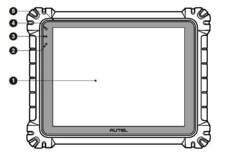
1. 12.9" TFT-LCD Capacitive Touch Screen
2. Ambient Light Sensor – detects ambient brightness
3. Power LED - refer to Table 2-1 Power LED Description for details
4. Front Camera
5. Built-in Microphone
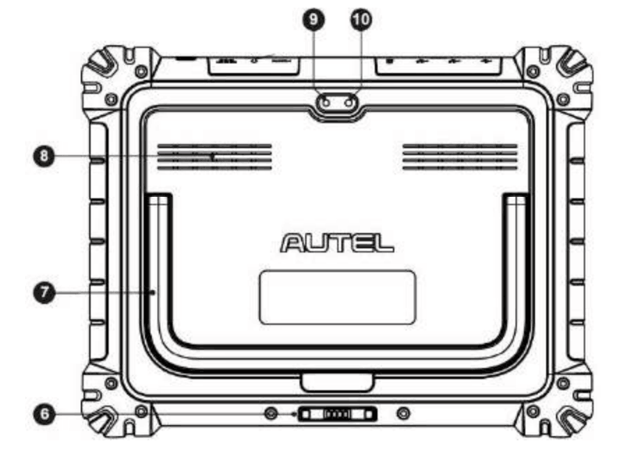
6. Docking Station Port
7. Collapsible Stand – extends from the back to allow hands-free viewing of the tablet
8. Speaker
9. Rear Camera
10. Camera Flash
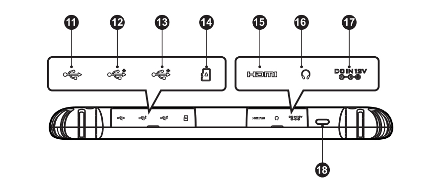
11. Mini USB Port – Cannot be used with the USB Port simultaneously
12. USB Port
13. USB Port
14. Mini SD Card Slot
15. HDMI (High-Definition Multimedia Interface) Port
16. Head Phone Jack
17. DC Power Supply Input Port
18. Lock/Power Button – long press to turn the on and off the Tablet, or short press to lock the screen.
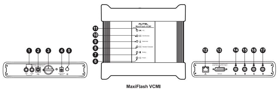
1. Multimeter Jacks
2. USB Port
3. Hook
4. DC Power Supply Input Port
5. Power Button
6. Power LED – refer to Table 2-4 Power LED Description for details
7. Battery LED - refer to Table 2-5 Battery LED Description for details
8. Waveform generator LED - lights green when operating in the waveform generator mode
9. Multimeter LED - lights green when operating in the multimeter mode
10. Oscilloscope LED - flashes green when operating in the oscilloscope mode
11. Vehicle LED - refer to Table 2-6 Vehicle LED Description for details
12. Ethernet Port
13. Vehicle Data Connector (DB26-Pin)
14. Input Channel A
15. Input Channel B
16. Input Channel C
17. Input Channel D